![]()
![]()
The following are notes on the dual dipole I have been using in Idaho since the year 2000.
For more than ten years I have been experimenting with multi-band dipoles which have a single feed point and no traps. Since 2000 I have been using such a dipole at my Idaho QTH. This dipole is designed to work on 80 meters and 40 meters and it has a single RG-213 feed line. The Q of the dipole is sufficiently high that I have installed 'jumpers' which add or subtract length to the antenna element that the antenna will present an SWR of less than 1.5:1 on either the phone portion or the CW portion of either band. Only one choice is possible for each band although one band can be set as CW and the other set as phone. The jumpers are changed manually by lowering the ends of the dipole and adding or removing the jumper. The antenna seems to operate with the efficiency one might expect from a dipole whose center is 46 feet above the ground. (about 0.175 wavelength on 75 meters). I am placing the construction information and dimensions on this web page in the event others may wish to try it.
The antenna is built from #14 aluminum wire (electric fence wire is $32.00 per half mile here in Idaho in 2002 - about 1.2 cents per foot) and fiberglass rod electric fence posts. The posts are 48" long and about 3/8" in diameter and cost about $1.00 each. Each post is cut to make three 18 inch spreaders. One half inch from each end of a spreader a 1/8" hole is drilled to accommodate the wire. In add ition to the 18 inch spreaders there are two 5 inch, two 9 inch and two 12 inch spreaders. A total of eight fiberglass posts is required (buy an extra in case you make a mistake). Wear a face mask when cutting and drilling the fiberglass rod to prevent particles from being aspirated
The dipole center is made from 1" PVC water pipe fittings and a short piece of the pipe. I happen to have built into the T-center a W2DU balun which has 50 beads. Another alternative would be to make a current balun that is placed either at the feed point or at a point closer to the ground. In any case, reducing or eliminating common mode currents flowing on the outside of the coax shield is highly desirable.
The PVC Tee I made allows me to place SS machine screws inside the end caps which can be used to mount the small aluminum brackets on each side of the T. These brackets permit compression clamping of the aluminum and eliminates trying to solder to the aluminum wire. The PVC - T and bracket assembly allows a significant amount of force to pull from the side without causing the antenna to 'disassemble'. Connection to the aluminum brackets is made by running silvered shield from RG300 coax from the ends of the bead balun inside the Tee tube to the bracket. (Sliver oxide is just about as conductive as silver and considerably more conductive than copper or copper oxide).
The lengths for the two dipoles almost certainly will be different for different locations and center heights but not by a great amount. They will be approximately 33' 6" on a side for the 40 meter phone band and 61' 2" for the bottom end of the 75 meter phone band. Attaching a 4 inch extension to the ends of the 40 meter phone band elements will move the low SWR point from the phone to the CW portion of 40 meters. Attaching a 6 foot extension to the 75 meter elements moves the low SWR point from the bottom of the phone band to the bottom of the 80 meter CW band. The 80 meter wire extension is a length of aluminum wire which is added to each end of the 75 meter dipole but separated from the actual end of the element by an insulator. I use a jumper across the insulator which is added or removed depending on which end of the band I want to operate on. The 80 meter jumpers are made of flexible wire and are 14 inches long . They have female spade lug connectors at each end which mate with male spade lug connectors on each side of the insulator.
It probably is worth noting that there are NO solder joints in the antenna --- everything is 'wire wrapped' or clamped. I guess the exception is the flexible wires that go into the body of the Tee. Those wires are silvered braid and are soldered internally to the bead balun and are crimped to terminal lugs that connect to the the aluminum bracket. These center bracket connections do not flex much in the wind.
The figures which follow will assist in understanding how things are assembled.
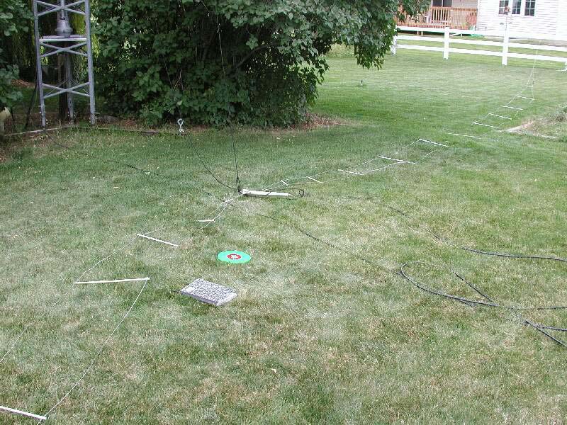
Figure 1 shows one entire side of the dual dipole. The first spreader is a 5" one, the second is a 9" one and the third is a 12" one. After that the next seven spreaders are 18 inches long. The last spreader is 6" long which brings the 40 meter element back toward the 75 meter element it is attached to. The insulator (black) at the end of the 40 meter element is visible as well. One end of that insulator connects to the 40 meter wire and the other is connected via nylon cord to an attachment point on the 75 meter wire. See Figures 2 and 3 below. The attachment point is formed by taking a small piece of wire and wrapping each end around the 75 meter element with a loop left between the wrap points. The main wire is left un-kinked but the friction of the wrapped wire keeps the attachment point in place.
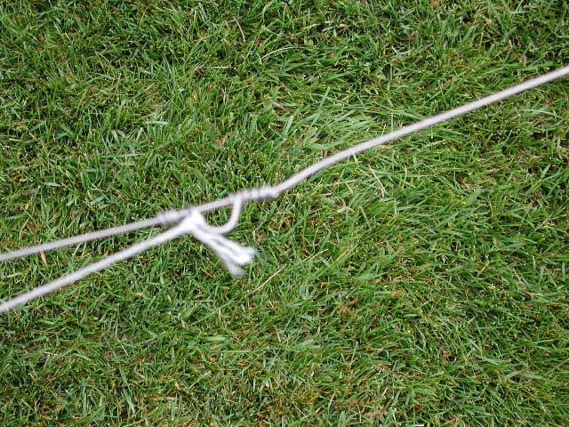
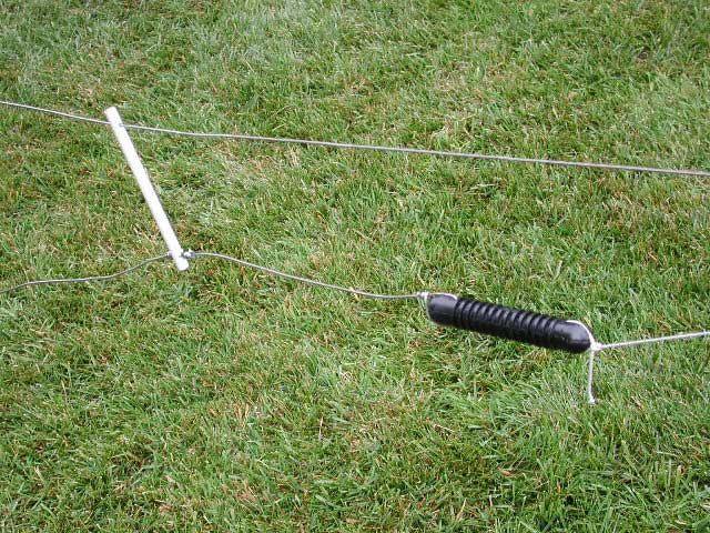
Figure 2 Figure 3
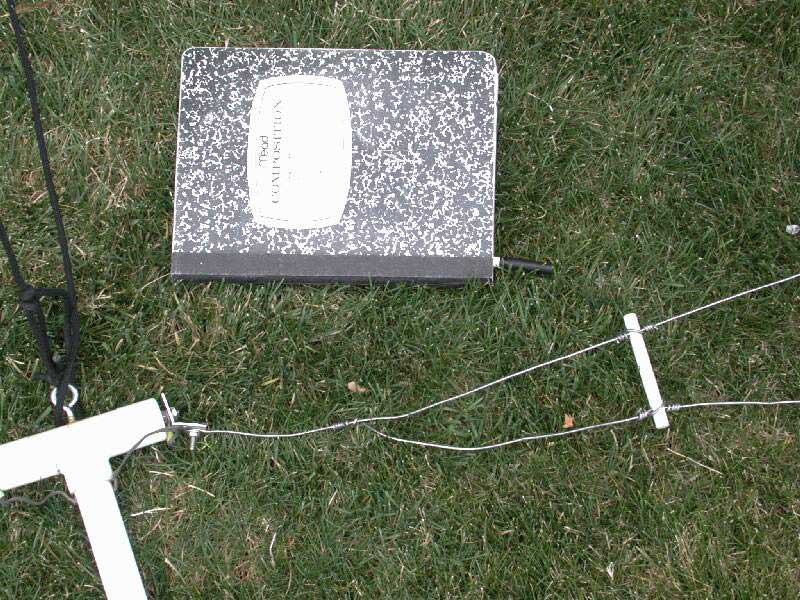
Figure 4
Figure 4 shows the PVC-T center and the aluminum end bracket used to clamp the aluminum wire. The silvered coax shield goes from the bracket into the tube and is connected to one of the bead balun ends. The 75 meter dipole wire is clamped and the 40 meter dipole wire is 'wire wrapped' to it.. About 5 tight turns around the wire and you have a connection that is as good as one that has been soldered. Because of the spreader arrangement there is no pulling stress on the 40 meter dipole, it simply hangs from the 80 meter dipole. The picture shows the "wire wrap" ties that hold the spreader in position on the element wires
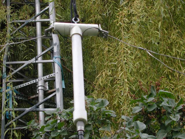
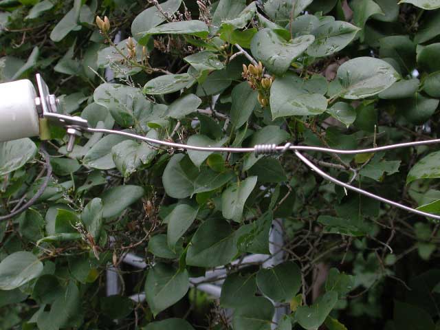
Figure 5 Figure 6
Figures 5 and 6 above provide additional views of the center Tee and the connections to the Tee.
Figure 7 below shows how a jumper used to add a length of wire to the 75 meter leg. The 75 meter leg is fastened to the left side of the insulator and the extra wire to provide resonance at the low end of the band is fastened to the right end of the insulator. The blue terminals at each end are male-female spade lugs which make it very easy to add or remove the jumper. The small piece of wire descending from the left hand side of the insulator is a tuning adjustment for the phone band frequency. I have it tuned for a lowest SWR point at 3.825 MHz.

Figure 7
Figure 8 below shows the tuning tail which is added to the 40 meter leg to adjust the lowest SWR point to 7.025 MHz. Again, I use male-female spade lugs on the wire ends to allow easy changes. My antenna has the low SWR point in the phone band set at 7.175 MHz.
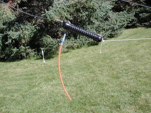
Figure 8
The dual-dipole is suspended from an arm extension mounted on a Rohn BX48 tower as shown in Figures 9 and 10 below.
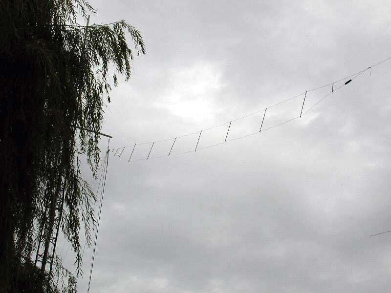
Figure 9
This picture was taken during one of the very rare cloudy days here in Idaho (... remember the song. "..and the skies are not cloudy all day"). It shows one side of the dual dipole hanging from a side arm on the top of the tower. The 80 meter end of the dipole is at 24 feet, the center is at 46 feet.
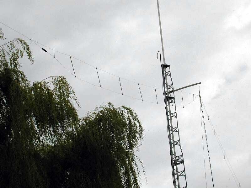
Figure 10
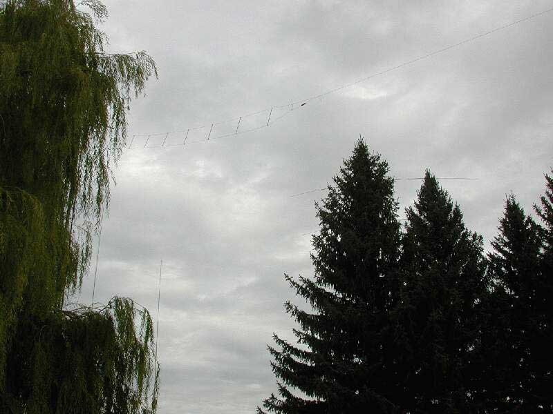
Figure 11
Figure11 shows the dual dipole in the foreground, the tip of my HyTower (160 and 80) in the lower center and an element of the Cushcraft 40-2CD 40 meter beam partially hidden by pine trees.
Figure 12, below, shows the tower and beams and the HyTower, but hides the dual dipole. I put it in just to give some perspective on the relative height of the 40 meter beam .and the TH7DXX triband beam The tower is about 2/3 of the way up in the picture; the tops of the pine trees are about 50 feet high. The Solarium of my house is barely visible in the center of the picture. The land in the foreground is mine, but is separated by an irrigation canal (I have water rights) from the trees, tower and house.
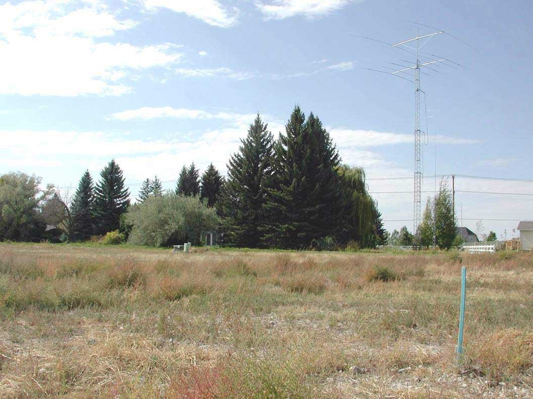
Figure 12
***************** End of article **************
![]()
![]()
![]()
![]()