![]()
![]()
Temperature Stabilized FT1000MP REF oscillator
In March of 2003 I checked the frequency of the REF oscillator in my FT1000MP using the process described in the note, “Checking and Setting the FT1000MP REF oscillator” on my web page. I found that not only was the REF oscillator frequency off after an hour using the radio, but that there was still a small amount of frequency drift after more than two hours of on time. After some discussion with Lyle, KØLR, I decided to install a positive temperature coefficient thermistor attached to the crystal can and see if that would not improve the stability.
The
REF oscillator board has a regulated +9 volt line which supplies the power to
the REF oscillator. (See schematic at end of this note). I followed the +9 volts back to the
regulator and estimated the amount of current that was being drawn from the
regulator by the various circuits that it feed. It looked to me as though I
could draw a constant 50 milliamps without any problem and probably could draw
as much as 90 milliamps at startup without a problem.
I
selected a 25 volt, 50 ohm (cold) thermistor [Mouser part number
527-3006-25v50/50C] for the variable resistance. Using a proto board I checked
the current drain for various resistors in series with the thermistor. A 68 ohm
resistor limited the startup current and allowed the thermistor to heat
sufficiently so that I could just feel that it was warm to the touch when
squeezed between my thumb and forefinger. At ‘full heat’ the current drain was
about 40 milliamps.
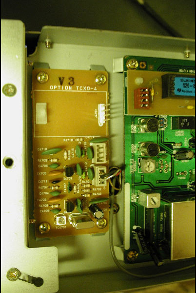
Figure 1
To
make the modification one must remove the REF oscillator board from the radio.
Remove the top and bottom covers and locate the board on the right front side
of the radio. Carefully pry out the cable which is plugged into the socket on
the board. Remove the four screws and lift out the board. See Figure 1 above.
The
thermistor is connected to one side of the crystal can. To do this I used an
XACTO knife to scrape off a thin line of the surface metal of the can from side
to side near the bottom of the can. Then using a 20 watt iron I quickly heated
the can and applied solder so that I had a thin line tinned across the can. I
positioned the thermistor so that the one lead (the one going to ground) was
running along the tinned line. I heated the thermistor lead with the soldering
iron and applied a bit more solder so that the thermistor was fastened to can
by one lead. I bent the thermistor so that its body contacted the can and could
transfer heat to the crystal. The
ground lead from the thermistor was dressed across the surface of the board and
bent under the board. There it was soldered to a ground pad.
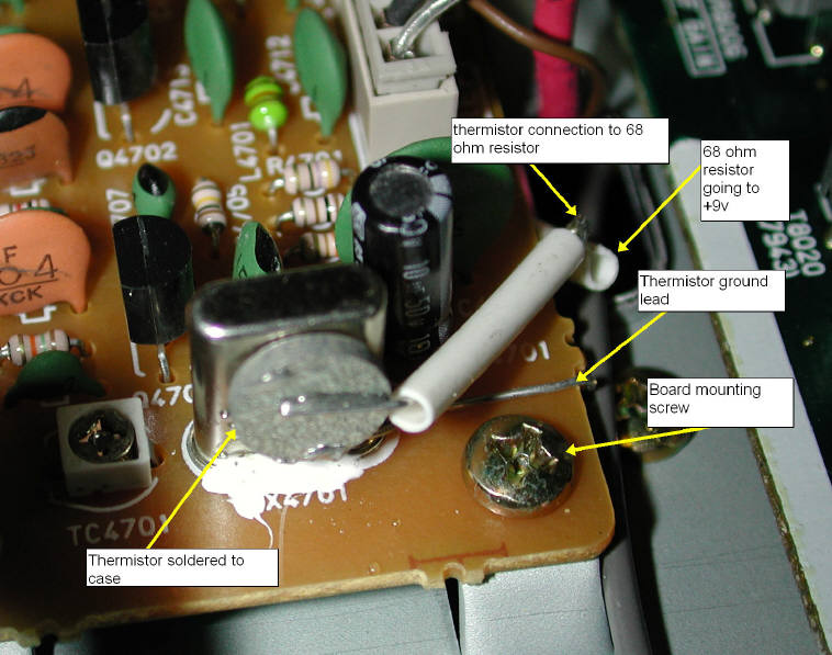
Figure
2
The
other thermistor lead (the +9v one) was cut about 3 inches from the thermistor. A 68 ohm,
¼ watt resistor was soldered to the lead and the combination bent under the
board to reach the +9 volt line on the plug socket of the REF oscillator.
Before soldering it to the 9 volt pad I pushed some insulated shrink wrap over
it to prevent shorting. See Figure 3
for the solder points.
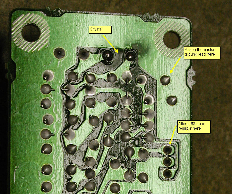
Figure
3 Location of pads for attachment of
resistor and thermistor.
After
adding the modification replace the REF oscillator board by reversing the
removal steps above. Then use the measurement and calibration method described
in “Checking
and Setting the FT1000MP REF oscillator” on my web page to adjust the oscillator to the correct frequency
and check the short and long term drift.
The modification gave me a short term drift such that that within two
minutes after turn on the REF oscillator was within 2Hz of the correct frequency and the long term
drift (two hours) stabilized at the desired frequency +/- ½ Hz. For a 10 MHz
oscillator this is 0.05 ppm. The schematic is shown in Figure 4 and the component layout
is shown in Figure 5 below.
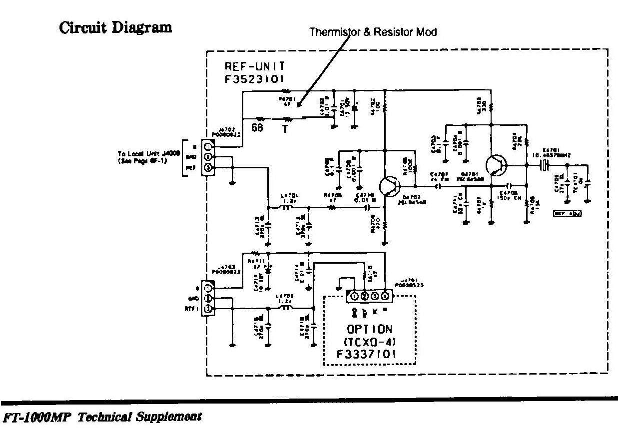
Figure 4 Schematic of REF Oscillator -- shows where the thermistor and 68 ohm resistor are added.
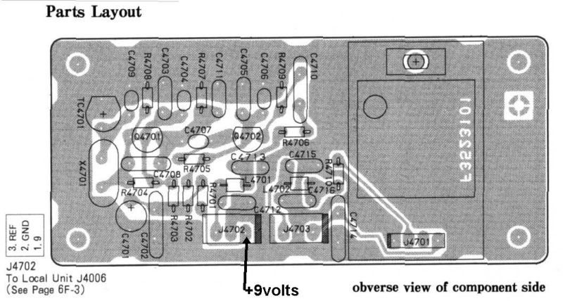
Figure
5. Component Layout
![]()
![]()