![]()
![]()
DUNESTAR 600 multiband filters
Revised
November 4, 2008 [added pictures of internals]
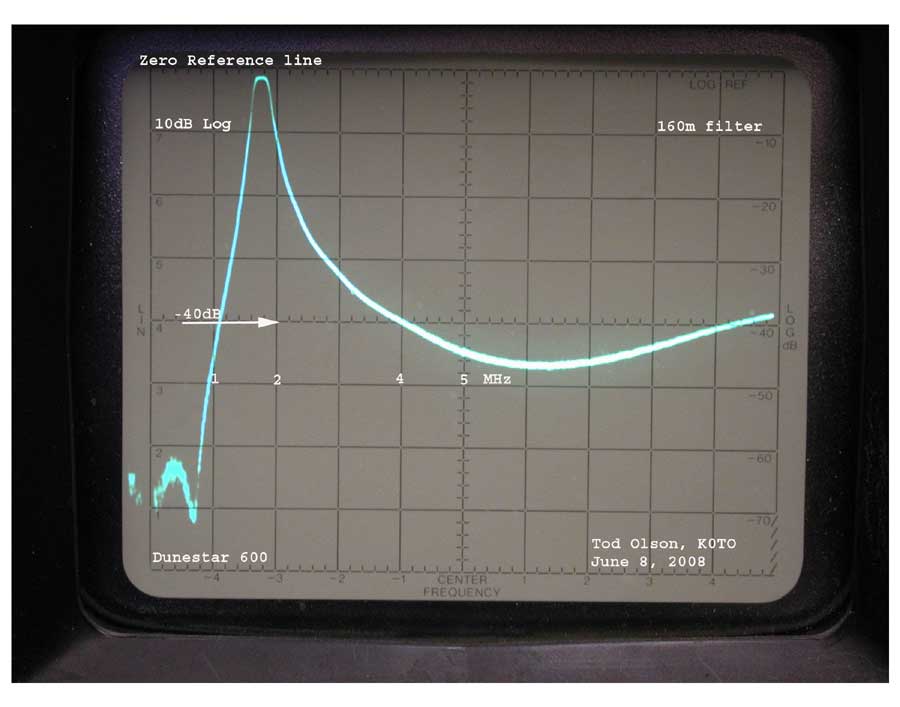
The pictures which follow were made using an HP-141T-HP8552B-HP8553B spectrum analyzer with an HP8444A tracking generator. The inital scans were performed on June 8, 2008 on a DuneStar Model 600 which was delivered on June 2, 2008 and probably manufactured in late May 2008. The unit was run into a 50 ohm resistive load. There may be changes in insertion loss and rejection if the load is significantly different from 50 ohms resistive.
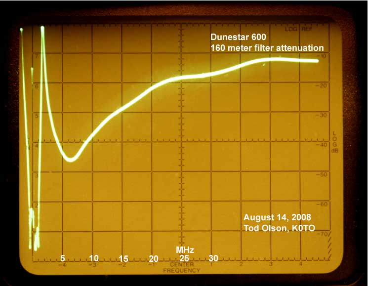
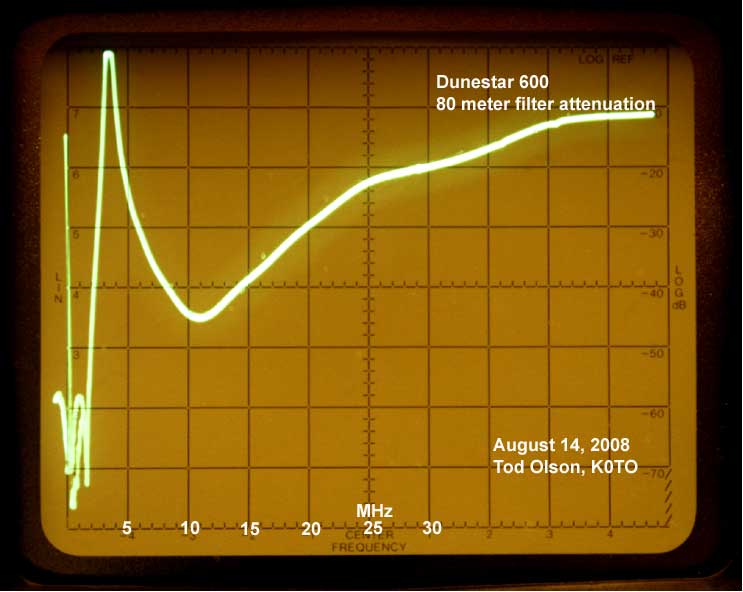
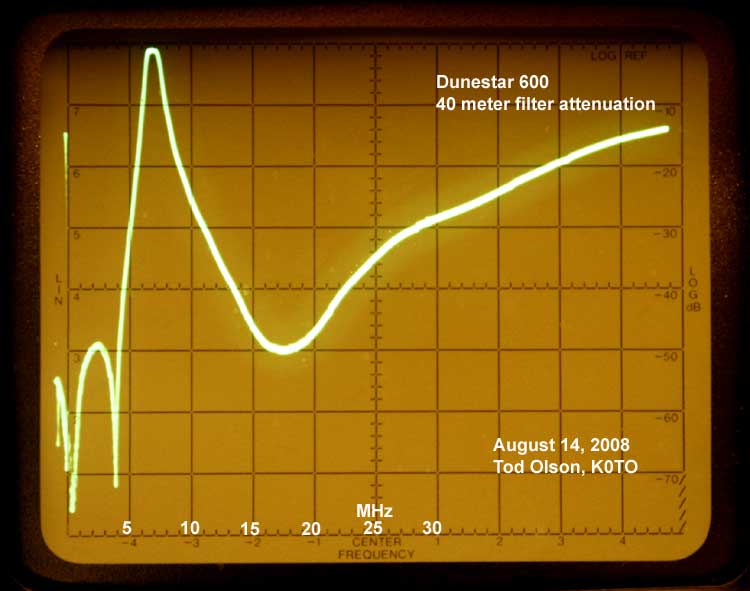
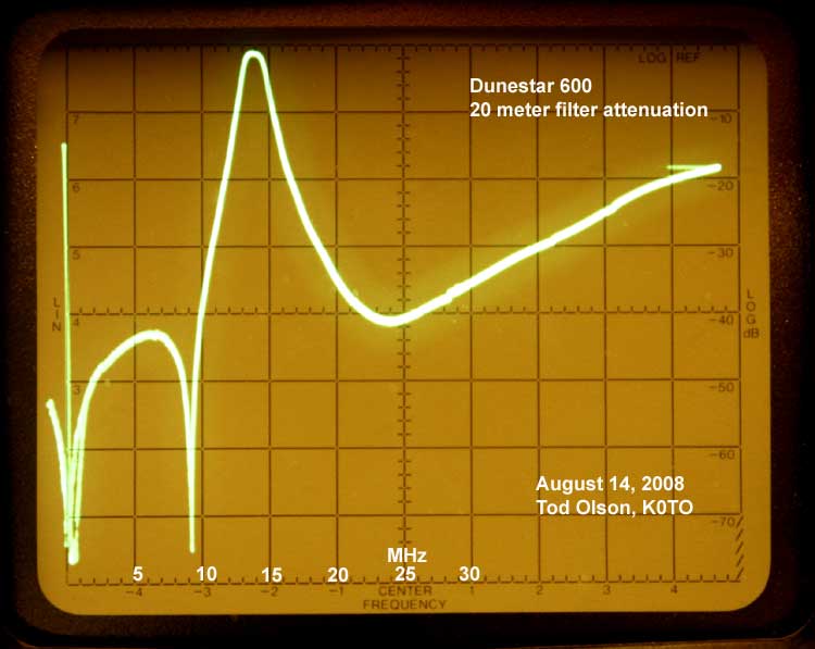
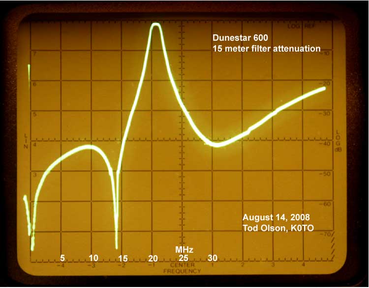
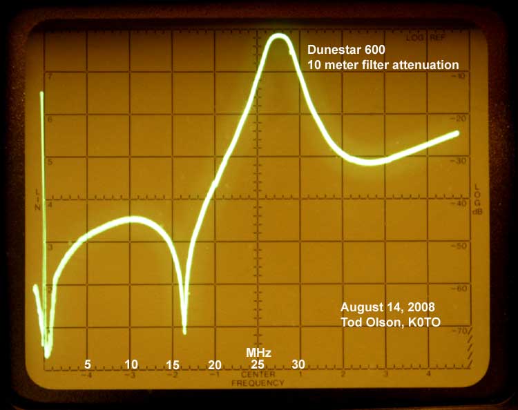
An additional set of scans were performed on August 14, 2008. These scans are located at the end of the paper. The scan range is 0-50 MHz with a scan width of 5 MHz per division. These scans show clearly the attenuation of each filter over the 0-50 MHz range making it easy to estimate the attenuation for frequencies above and below the pass band frequencies.
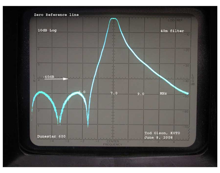
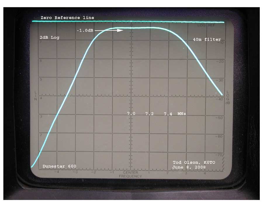
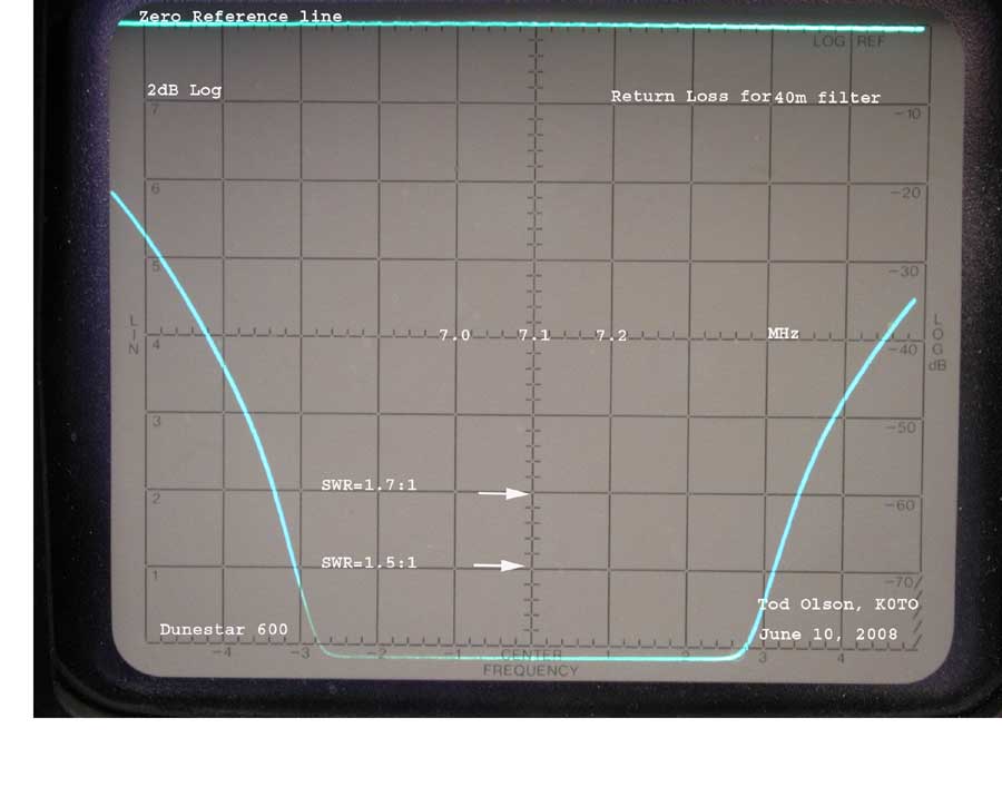
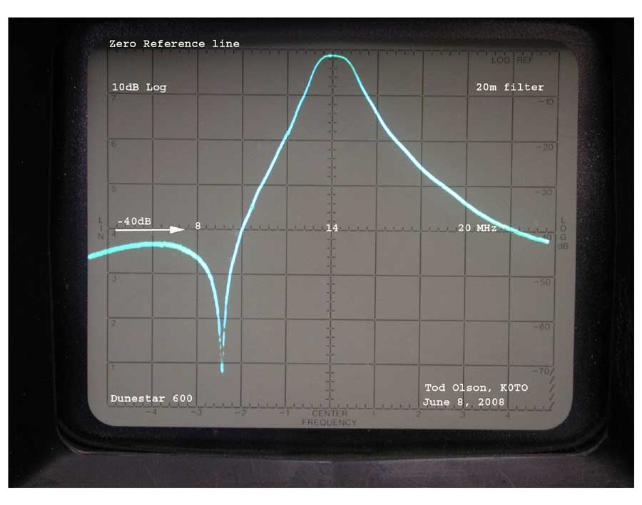
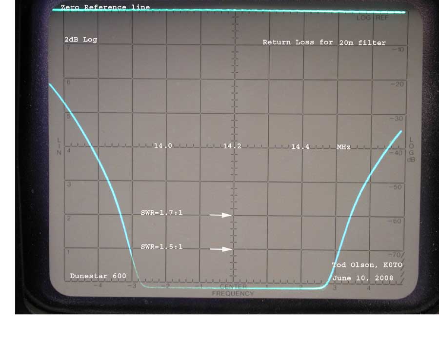
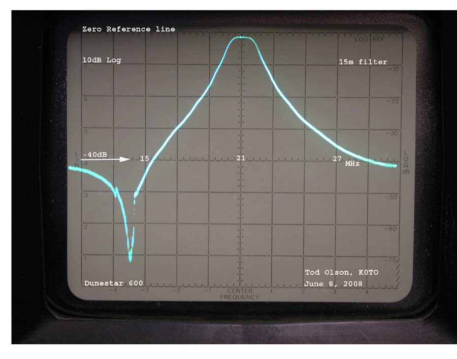
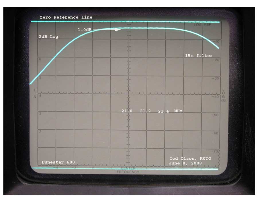
There initial scans produced three pictures for each band, One picture shows the pass band rejection over a wide frequency range -- generally showing the sub-harmonic frequency and the first harmonic frequency. The display scale is 10 dB per division. The second picture in each set shows the pass band insertion loss. The display scale is 2 dB per division. The third picture shows the return loss of the filter when terminated in a 50 ohm load.
The DuneStar 600 manual states the specifications for the filter set as:
Insertion Loss: Typical, 0.5-0.7 dB
Rejection: Typical, 40dB band-to-band
Bandwidth: VSWR <1.5:1 typical
160M 1.8- 1.93
80M 3.5- 3.85
40M 7.0- 7.30
20M 14.0-14.35
15M 21.0-21.50
10M 28.0-28.70
Each of the DuneStar filters is manually tuned during production so the measurements I recorded are specific to this unit and may not apply to others. In discussion with the factory they felt that the differences between units is small.
Results of my measurements on this unit:
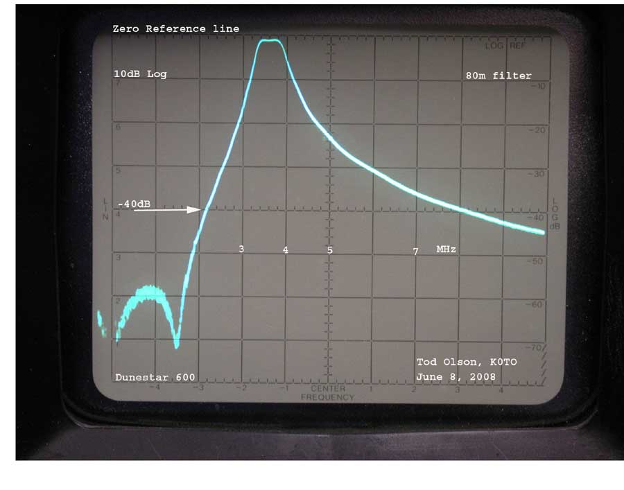
1. My measurements show for these filters in every case the band rejection attenuates the sub-harmonic by at least 40 dB and the first harmonic by at least 35 dB.
Rejection: *
|
Band |
Band down |
Band up |
|
160m |
NA |
38 dB |
|
80m |
50 dB |
36dB |
|
40m |
50 dB |
45 dB |
|
20m |
45 dB |
38 dB |
|
15m |
45 dB |
38 dB |
|
10m |
35 dB |
NA |
* See the 0-50 MHz scans at the end of the paper.
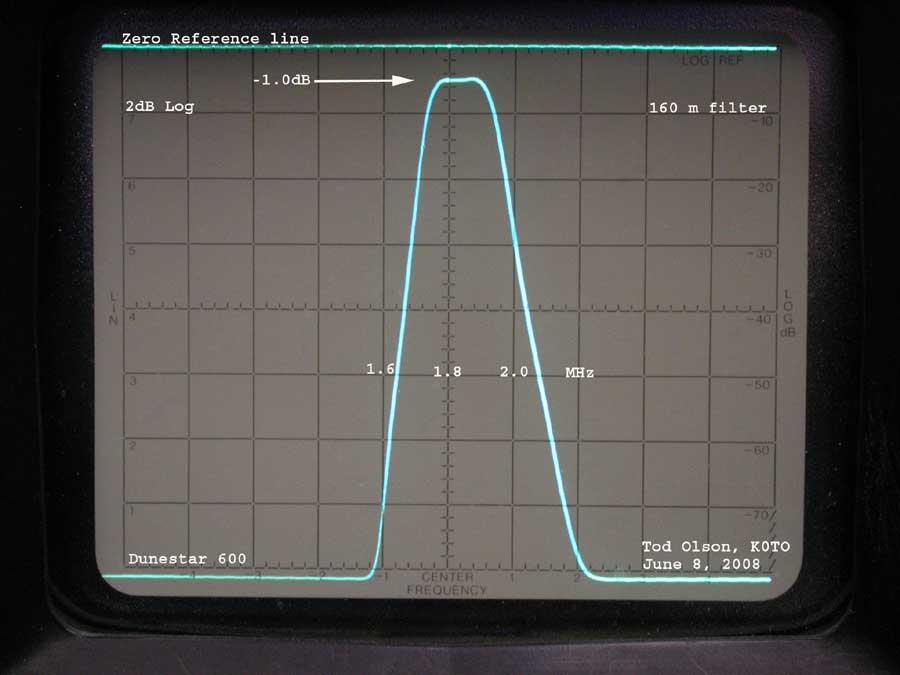
2. On every band I found the insertion loss to be slightly greater than the spec, by about 0.1 dB. My spectrum analyzer probably is not really able to accurately measure to the nearest 0.1 dB so these results probably conform to the spec. More than that, I don't think that an additional 0.1 dB of loss would be at all noticeable -- at least not for me.
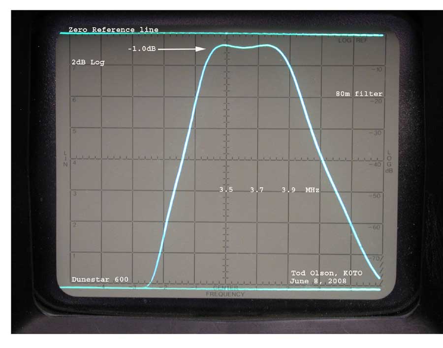
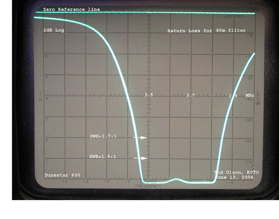
3. The bandwidth specifications are met for all bands except 80 meters. On 80 meters the 1.5:1 VSWR bandwidth seems to be from 3.45-3.84 kHz instead of 3.50-3.85 kHz. That is a very small difference. However, if you operate above 3860 the VSWR will be 1.9:1 or greater and it may affect the output of your solid state transmitter. The reflected power is 10% at 1.9:1 so in the case of a 200 watt transmitter about 20 watts will be lost as heat in the filter.
Observations:
The attenuation of the filters seems appropriate for three pole filters. The
only unexpected thing was with respect to the 80m filter. The pass band of
interest seems a bit low, starting at 3450 and going to 3840 or with VSWR of
1.5:1 Because the filter rolls off so fast the losses at 3860 and above may
generate undesirable heat. However, because the
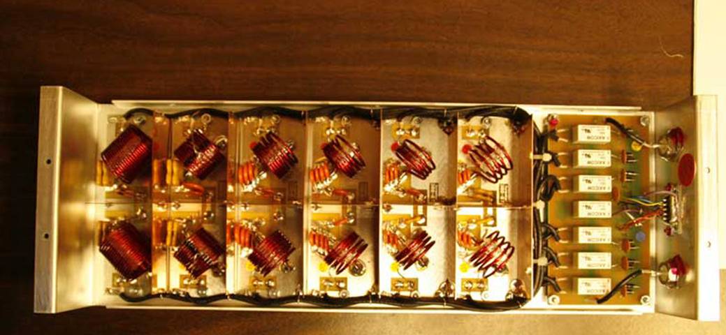
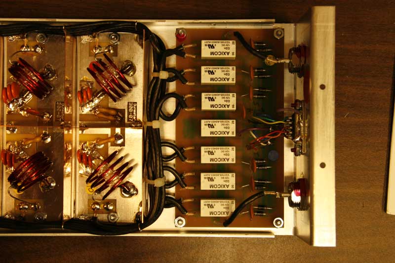
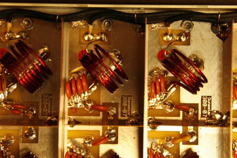
It is my feeling that this filter unit will perform in accordance with one's expectations for a filter with these specifications. The internal construction is excellent. No tests were made [yet] running power through the filters. Prudent operation dictates that the bands are not switched with RF power going into the filter. The pictures below show the construction detail.
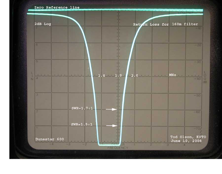
The 160 meter filter.
Attenuation
Pass
Band Loss
VSWR
The 80 meter filter.
Attenuation
Pass
Band Loss
VSWR
The 40 meter filter.
Attenuation
Pass
Band Loss
VSWR
The 20 meter filter.
Attenuation
Pass
Band Loss

VSWR
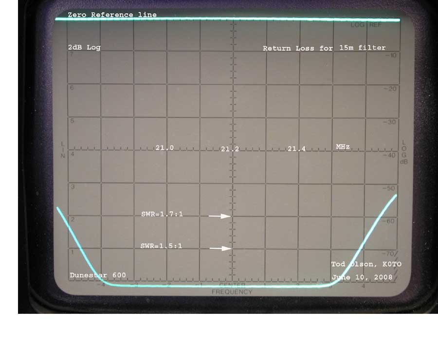
The 15 meter filter.
Attenuation
Pass
Band Loss
VSWR
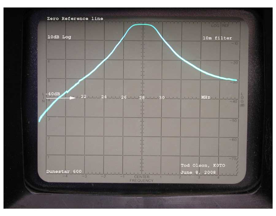
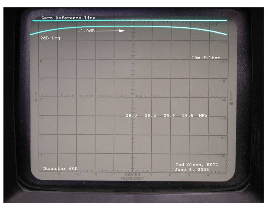
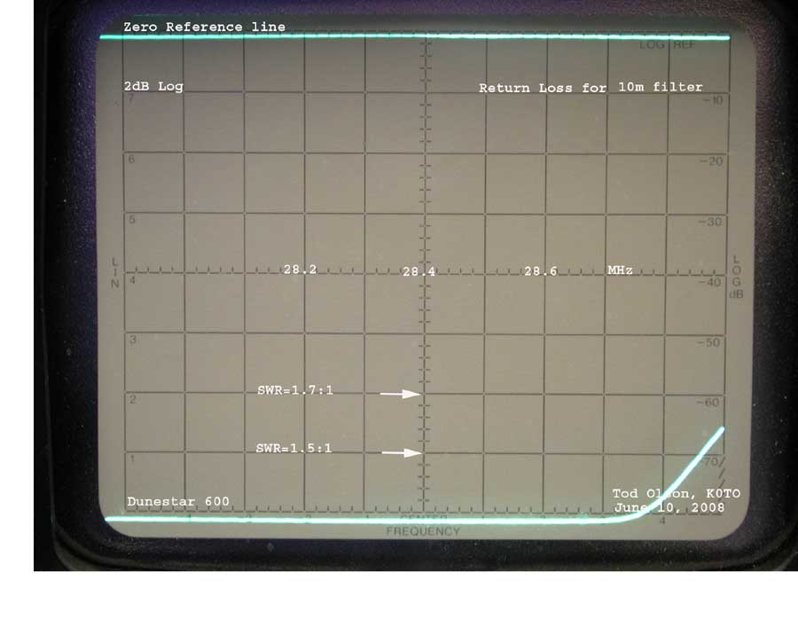
The 10 meter filter.
Attenuation
Pass
Band Loss
VSWR
The following scans show the attenuation over the frequency range 0-50 MHz for each of the filters.
End